AI Datacentre Behind-the-Meter Power
A high-temperature exhaust-recovery wedge inside the AI behind-the-meter power buildout. At suitable turbine and reciprocating-engine sites, MicroPower models a system-level recovery case of 5–7.5%, subject to site-specific thermal design, cold-side integration, parasitic load and OEM constraints.
The BTM Buildout Is the Biggest Thermal Opportunity of the Decade
Hyperscalers are installing gas generation on-site because the grid cannot deliver power fast enough
xAI, Meta Hyperion, OpenAI Stargate, Oracle/VoltaGrid, AWS and Google combined through 2028
Aeroderivative and industrial turbines – prime territory for PbTe / TAGS TEG modules
Indicative wedge on top of simple-cycle engines at suitable sites. Derived from 10–15% module-level efficiency at design conditions × ~50% system derate (heat-exchanger ΔT loss, cold-side parasitic, ducting, contact resistance, packing factor). Actual outcome depends on site-specific thermal design and OEM constraints.
Why BTM, Why Now
The grid interconnect queue is multi-year; AI training runs cannot wait
Training a frontier model at 500 MW–1 GW of campus load requires power available in months, not years. Utility interconnect queues in PJM, ERCOT, and MISO currently quote 4–7 year timelines for new large loads. Hyperscalers have responded by putting primary generation on the customer side of the meter:
- xAI Colossus (Memphis, TN): 35 Solar / Mitsubishi SMT-130 turbines, ~742 MW – Phase 1 live 2024, Phase 2 in permitting
- Meta Hyperion (Richland Parish, LA): 7 GW+ campus with on-site combined-cycle and peaking turbines
- OpenAI Stargate (Abilene, TX): 11 GW+ target, multi-site, gas-primary interim supply
- Oracle / VoltaGrid (multi-site): 2.3 GW+ across Texas and Nevada on Wärtsilä 31SG and Innio Jenbacher J920 packages
- AWS and Google: 15 GW+ and 5 GW+ respectively in various stages of planning and permitting
These campuses share one problem: simple-cycle engines reject 55–65% of fuel energy as hot exhaust. At $3.50–5.00/MMBtu gas and 24×7 training loads, every percentage point of electrical efficiency is worth eight-figure annual dollars per campus.
Engine Families and Exhaust Profiles
Where MicroPower PbTe / TAGS modules fit on the BTM generation stack
| Engine Class | Representative Units | Exhaust Temp | TEG Fit |
|---|---|---|---|
| Aeroderivative turbines | GE LM2500, LM6000, Siemens SGT-A35 | 450–510°C | PbTe hot-side, ideal |
| Industrial frame turbines | Siemens SGT-600 / SGT-800, MHI H-25 | 509–630°C | PbTe + TAGS, optimal band |
| Large reciprocating gas engines | Wärtsilä 31SG, Innio Jenbacher J920 | 370–450°C | TAGS / mid-temp PbTe |
| Mid-size reciprocating | Jenbacher J620, MWM TCG 3016, CAT CG170 | 380–440°C | TAGS, good match |
Exhaust temperatures shown are typical at full load; turndown and ambient conditions shift these by 20–60°C. MicroPower's PowerRing geometry wraps the exhaust duct without adding backpressure beyond the engine OEM's allowable envelope (typically < 25 mbar).
TEG and ORC Are Complementary, Not Competing
The honest framing: an ORC recovers the bulk; TEG polishes the tail
Organic Rankine Cycle (ORC) systems are the incumbent for turbine exhaust recovery at utility scale. On a 50 MW aeroderivative, an ORC adds 6–9% net electrical output by cooling exhaust from ~500°C down to ~180°C. That is the right technology for that duty and that temperature drop.
But on a BTM site the stack looks different:
- Engine plus ORC leaves a residual tail from ~180°C down to stack exit at 120–150°C. TEG modules capture part of that tail without the water, steam loop, or condenser footprint ORC requires.
- On reciprocating stacks (under 50 MW), ORC economics get tight below about 10 MW thermal. TEG scales linearly from single-engine 2–4 MW packages up, with no minimum-viable size.
- In water-constrained sites (West Texas, Nevada, interior Australia), ORC condenser water or air-cooled towers are a permitting and capex problem. TEG requires neither.
- For modular, drop-in retrofit, TEG ships as a PowerRing sleeve around the existing exhaust duct – weeks of install, not months.
For hyperscaler customers building portfolios of 50+ engines across multiple campuses, the right question is not "TEG vs ORC" but "where does each fit in the exhaust cascade, and what is the combined uplift?"
The Permitting Angle: Every BTU Recovered Is a BTU Not Combusted
System-level recovery may support an efficiency and emissions-intensity argument in permit discussions
BTM gas generation at AI datacentre scale frequently triggers New Source Review under the Clean Air Act, with NOx, CO, VOC, and PM2.5 netting analysis on the commissioning critical path. Every percentage point of electrical efficiency added to the stack reduces fuel burn per MWh delivered, and therefore reduces emissions per MWh of compute.
A modelled 5–7.5% system-level recovery on a 500 MW campus (assumptions as above: 10–15% module-level efficiency at design conditions × ~50% system derate covering heat-exchanger ΔT loss, cold-side parasitic, ducting, contact resistance, packing factor) would correspond to:
- Estimated gas consumption reduction of ~5–12 Bcf/year (at 70% capacity factor)
- Estimated avoided emissions of ~300,000–700,000 tonnes CO₂-equivalent per year
- Proportional reductions in NOx and PM, which may support NSR netting and community-relations narratives
Formal treatment in a Best Available Control Technology (BACT) determination or NSR netting analysis would depend on the permitting authority, site design and the chosen emissions model. For a developer working a contested permit, TEG recovery offers a quantifiable efficiency lever alongside its revenue contribution.
Ideal First Deployment Profile
Where a TEG retrofit pays back fastest
Site Characteristics
- Simple-cycle gas engines 2–50 MW, typically aeroderivative or large reciprocating
- 24×7 training or inference loads (>70% capacity factor)
- Water-constrained or ORC-rejected site
- Existing NSR permit pressure or community-relations concerns
- Phased expansion – first engines delivered 2025–2026, additional units 2026–2028
Commercial Characteristics
- Anchor hyperscaler or their BTM developer/EPC (Crusoe, VoltaGrid, Generac Industrial, Caterpillar Energy Solutions)
- Design-in window open through late 2026 before engine-island freeze
- Appetite for first-of-a-kind deployment with structured, milestone-based performance criteria
- Bundled ORC + TEG cascade optioned into the master equipment list
Where MicroPower stands today
MicroPower's modules have been proven in proof-of-concept tests in real, high-temperature industrial conditions, and independently validated. What has not yet happened is commercial deployment at scale.
That gap is not about whether the technology works – it does. It is that commercialising it needs a manufacturing capability and the capital to build it, which the company is now working to put in place. The opportunity set out on this page is a near-term target built on that validated platform, not a deployed product today.
Flagship White Paper
The full technical and commercial case, 7 pages
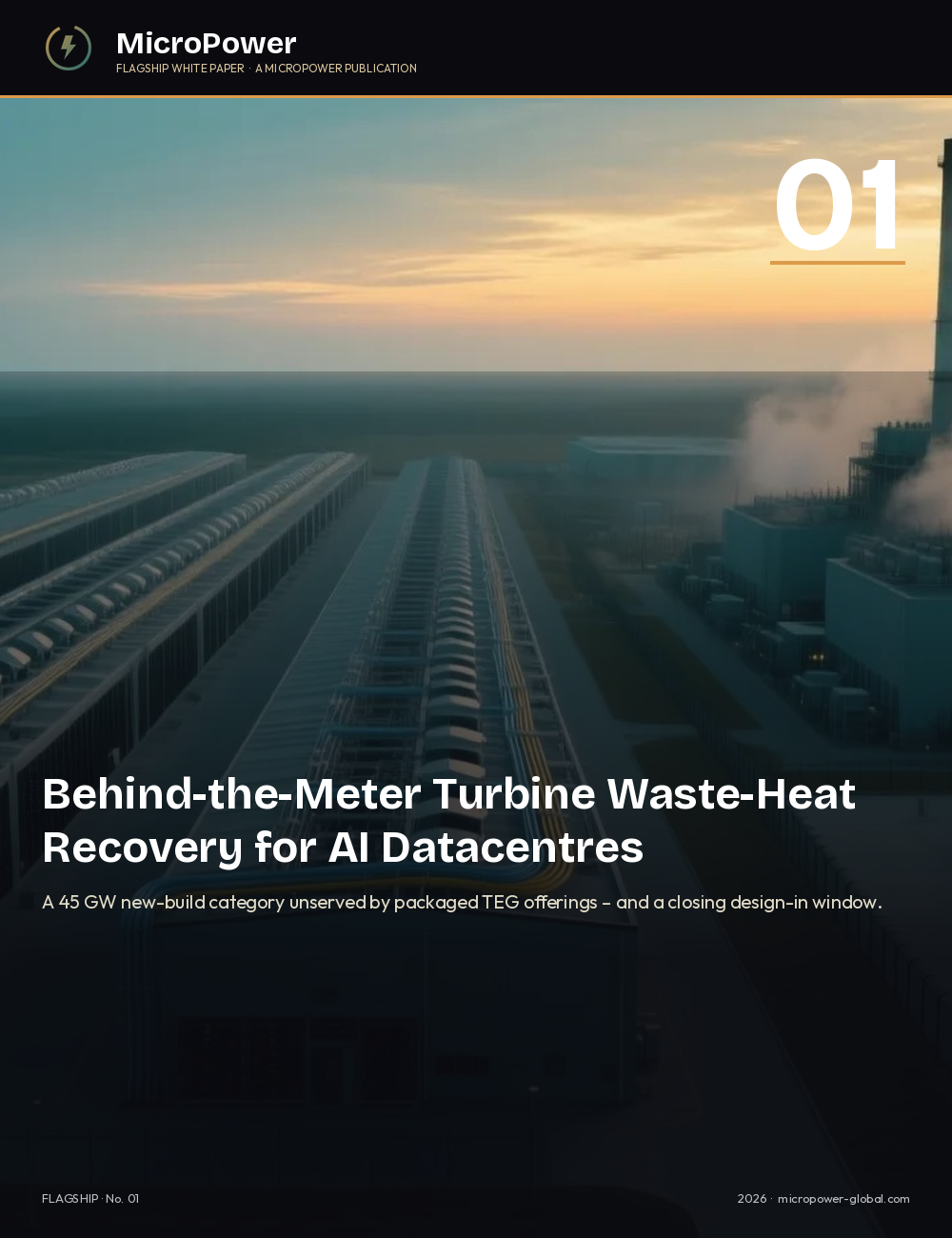
WP-A · AI Datacentre BTM Turbine Waste-Heat Recovery
Hyperscaler behind-the-meter capacity by site, engine-family exhaust profiles, TEG + ORC complementary stack economics, NSR emissions-mitigation angle, and go-to-market channel ranking through the 2026 design-in window.
Related Sectors
Industrial Waste Heat
Steel, cement, glass, refining and hydrogen DRI – the largest stationary waste-heat pools on the planet.
Bioenergy & Biogas
CHP engine exhaust recovery for sub-1 MW anaerobic digestion and biomass sites.
Thermal Storage Discharge
Steady high-temperature heat from molten salt, particle and refractory thermal batteries.